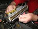
Schedule December 2006
return to main 1401 Restoration Page
go to Team Bios
Contents:
Fri Dec 01 - Tape Team,
Wed Dec 06 - general,
Thu Dec 07 - Tape Team,
Sat Dec 09 - 2nd Sat,
Wed Dec 13 - general ,
Thu Dec 14 - Tape Team,
Wed Dec 20 - general,
Fri Dec 01 - Tape Team,
and follow up e-mails
Wed Dec 06 - general,
I just read your log entry about the 1402 problem when there are lots of
holes in the card. This was a common problem with all card readers that
used read brushes to flip cores. It first showed up on the 714 card
reader after the Column Binary feature was installed to read binary
cards.
The most common cause was low voltage getting to the contact
roll. This could be caused by low voltage out of the power supply or
anything causing high resistance from the supply to the roll. Some of
the causes were worn or burned common brushes, loose screws in terminal
blocks and frayed or broken wires. I wrote a detailed story about my
first encounter with this problem in my story # 23 Chinese Binary.
The best way to see if this is your problem is to put one scope probe on
one of the brush wires where it plugs into the connector block. Put the
other scope probe on the output of the voltage supply and run some cards
that have all the holes in the 4 row punched. When the 4 row feeds
past the read brushes you will see a square wave and can measure the
voltage on the roll. If it is much different than the supply you can
move the second probe along the wiring path from the supply to the
common brush and tell where the difference occurs.
Van Gardner
Received from John Van Gardner - Dec 4, 2006
The row bit cores are in the 1401 array and I marked with red where the
-20 attaches. There is a chart on page 42.40.53.2 that shows the actual
pin connections to the array. Also marked is a note that says,
"Machines with serial numbers above 25000 have 1/2 write line removed.
This allows the row bit core to set with full I from read brush".
ALD page 42.40.51.1 has a chart that show the connections between row
bit cores and the read brushes. There is a note at the bottom of this
chart that says, "All brush signal lines have a 180 ohm series resistor
before 01A1 edge connector termination on the paddle card connector". I
wondered if this resistor value is the same for all serial number 1401s.
When they did away with the 1/2 write line how did they increase the
current through the brush? Assuming no other resistance 21 volts
through a 180 ohm resistor = 117ma. If you have all 80 columns punched
in the same row that's 9.3 amps from the supply and through the
transistors driving the common brush. Any resistance in the common
circuit could explain why it fails when there are lots of holes punched.
Van Gardner
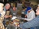
Wednesday finally came, and seven dwarfs went to "work" -
Thu Dec 07 - Tape Team
TAU Debug:
Miscellaneous:
Regards,
Sat Dec 09 - general
Star errors when reading or punching a card - false errors
Troubles writing/reading tape drive - 8 bit dead ? where?
Bob Feretich on vacation until mid Jan.
Wasn't a volunteer day? - no free food - Jim Somers owes us ;-))
Addendum to previous Thursday report- e-mail between Robert Garner and Bob Feretich
Wed Dec 13 - General
It was rumored that Robert was meeting with the museum's restoration committee :-|
The game was to reduce the current through the pick coil during the hold operation. (It requires a lot
more magnetism to pull in a relay than to hold it in the pulled-in position. That is a reason many
relays use two coils.) Our pick coil is 1.2 K ohm, excited by 160 volts. The calculated power dissipation is about 21 watts :-((
I imagine as the coil heats the resistance increases - but not by enough. The target resistance of the open hold coil
was about 3.3 K ohms.
Lets not mention blowing the 2 amp slow blow power supply fuse while probing about. And the anguish of replacing it with
the only practical fuse we had - a 5 amp fast blow.
In any case we decided to place a little electric lamp in series with the jumper "we" installed between the pick and hold coil,
as suggested in an e-mail, to reduce the voltage on the coil during hold time. Now - what wattage lamp??
We measured the resistance of a 7 watt Christmas bulb, and watched the cold resistance of 183 ohms rise past 200 ohms as the
slight current from the ohmmeter heated the tungsten filament. - Oh boy, OK time for experimentation as we had neither
the resistance coefficients nor the inclination to try to calculate and guess several unknowns.
The results were very positive :-))
We also tested the above circuit with a 4 watt bulb - but the hold in force was judged "marginal".
It is interesting to watch experienced CEs removing jams. The first thing is to mark the cards with
their estimated sequence position - so that when the cards are removed,
(and de-wrinkled and maybe re-keypunched) the deck can be ordered as correctly as possible.
And there also appears to be a time handling timing problem? Bob Feretich wrote a tape full of "V"s last week,
and when different test was run, not only was bit 8 missing of the records written in this test,
Thu Dec 14 - Tape Team
Wed Dec 20 - general
Merry Christmas, Happy Holidays, :-))
TAU & Tape Drive debug status: Dec 1, 2006 (Jeff. S and me)
Drive debug status:
TAU debug status:
I suspect a bad signal level in the error detect circuitry.
Regards,
Bob
The 1402 problem I reported is not "gang punch" related.
I believe the bug is in the 1401 CPU address generation circuitry.
Regards,
Bob
--- Robert Garner
Received from John Van Gardner - Dec 3, 2006
Robert,

1401 Maint Manual page 95
I was looking at the 1401 Maintenance Manual 225-6487-3 pages 180 and
181 which show scope pictures and set up to check the read brushes and
impulse CBs. There is a good diagram on page 95. I wish I knew some
way to capture one page of a .PDF file and send it
Robert B Garner wrote:

John,

Thx for your note.
A 9.3-amp pulse to our old 1402 21V power supply could be our issue.

I'm not familiar with required core switching currents (in general, and wrt 1401).
Is 117 mA already a marginal value?
The only cores that I actually knew what the switching currents were in the 737 memory on the 704. We had to scope the terminator resistors for the X and Y array drive lines and look for a voltage level that represented 410ma +or- 10ma. These X and Y drive lines only went through the hole in 64 cores one time. We did not have any vacuum tubes that could supply this amount of current so that's why they used switch cores to drive them. As cores became smaller with less mass it took less current to flip them. The cores in the 7302 memory on the 7090 could pass through the hole in a 737 core. Then the 360 cores could pass through the hole in the 7302 cores.
What does it mean to "remove 1/2 write line"?
Why would they do that?  (cost optimization?)
If you look at the left hand red arrow on the attached diagram you will see it points to a line labeled 1/2 write * that goes from the power transistor up through a resistor then over to the right and down through the row bit core. This is the line that was removed on the 25000 serial number machines. This would certainly help reduce the cost of the array as these were all hand wired at that time.
There is a second line from the power transistor through the read brush then through a resistor then to the row bit core. Notice that when this line goes through the core it is wrapped around the core several times then to the -20 volts. The extra turns help flip the core with less current.
Robert B Garner wrote:

Van,

Thanks for your advice!
I suspect it will help us immensely again.

> We had to scope the terminator resistors for the X and Y
> array drive lines and look for a voltage level that represented 410ma +or- 10ma.

I've been trying to encourage the guys to do exactly this
to find out what's wrong with our extended core memory.


> There is a second line from the power transistor through
> the read brush then through a resistor then to the row bit core.

It's amazing that the current directly from the read brushes
is used to flip a core in main memory!
(Imagine all the junky noise that could get on it
    via the ground loop formed between the 1401 and the 1402
in a noisy environment due to nearby elevators, etc.).

- Robert
                               JJJJJJ  UU      UU  DDDD        YY      YY
                              JJJJJJ  UU      UU  DDDD        YY      YY
                                JJ    UU      UU  DD    DD    YY      YY
                                JJ    UU      UU  DD    DD    YY      YY
                                JJ    UU      UU  DD      DD  YY      YY
                                JJ    UU      UU  DD      DD  YY      YY
                                JJ    UU      UU  DD      DD    YY  YY
                                JJ    UU      UU  DD      DD    YY  YY
                                JJ    UU      UU  DD      DD      YY
                                JJ    UU      UU  DD      DD      YY
                          JJ    JJ    UU      UU  DD    DD        YY
                          JJ    JJ    UU      UU  DD    DD        YY
                            JJJJ        UUUUUU    DDDD            YY
                            JJJJ        UUUUUU    DDDD            YY

                GGGGGG      AAAAAA    RRRRRRRR    LL            AAAAAA    NN      NN  DDDD
                GGGGGG      AAAAAA    RRRRRRRR    LL            AAAAAA    NN      NN  DDDD
              GG      GG  AA      AA  RR      RR  LL          AA      AA  NN      NN  DD    DD
              GG      GG  AA      AA  RR      RR  LL          AA      AA  NN      NN  DD    DD
              GG          AA      AA  RR      RR  LL          AA      AA  NNNN    NN  DD      DD
              GG          AA      AA  RR      RR  LL          AA      AA  NNNN    NN  DD      DD
              GG  GGGGGG  AA      AA  RRRRRRRR    LL          AA      AA  NN  NN  NN  DD      DD
              GG  GGGGGG  AA      AA  RRRRRRRR    LL          AA      AA  NN  NN  NN  DD      DD
              GG      GG  AAAAAAAAAA  RR  RR      LL          AAAAAAAAAA  NN    NNNN  DD      DD
              GG      GG  AAAAAAAAAA  RR  RR      LL          AAAAAAAAAA  NN    NNNN  DD      DD
              GG      GG  AA      AA  RR    RR    LL          AA      AA  NN      NN  DD    DD
              GG      GG  AA      AA  RR    RR    LL          AA      AA  NN      NN  DD    DD
                GGGGGGGG  AA      AA  RR      RR  LLLLLLLLLL  AA      AA  NN      NN  DDDD
                GGGGGGGG  AA      AA  RR      RR  LLLLLLLLLL  AA      AA  NN      NN  DDDD

  V   V  III   SSSS  III  TTTTT EEEEE DD          TTTTT H   H EEEEE        CCC   OOO  M   M PPPP  U   U TTTTT EEEEE RRRR
  V   V   I   S       I     T   E     D  D          T   H   H E           C   C O   O MM MM P   P U   U   T   E     R   R
  V   V   I   S       I     T   E     D   D         T   H   H E           C     O   O M M M P   P U   U   T   E     R   R
  V   V   I    SSS    I     T   EEEE  D   D         T   HHHHH EEEE        C     O   O M M M PPPP  U   U   T   EEEE  RRRR
  V   V   I       S   I     T   E     D   D         T   H   H E           C     O   O M   M P     U   U   T   E     R R
   V V    I       S   I     T   E     D  D          T   H   H E           C   C O   O M   M P     U   U   T   E     R  R
    V    III  SSSS   III    T   EEEEE DD            T   H   H EEEEE        CCC   OOO  M   M P      UUU    T   EEEEE R   R

                    H   H  III   SSSS TTTTT  OOO  RRRR  Y   Y       M   M U   U  SSSS EEEEE U   U M   M
                    H   H   I   S       T   O   O R   R Y   Y       MM MM U   U S     E     U   U MM MM
                    H   H   I   S       T   O   O R   R Y   Y       M M M U   U S     E     U   U M M M
                    HHHHH   I    SSS    T   O   O RRRR   Y Y        M M M U   U  SSS  EEEE  U   U M M M
                    H   H   I       S   T   O   O R R     Y         M   M U   U     S E     U   U M   M
                    H   H   I       S   T   O   O R  R    Y         M   M U   U     S E     U   U M   M
                    H   H  III  SSSS    T    OOO  R   R   Y         M   M  UUU  SSSS  EEEEE  UUU  M   M

   AAA  PPPP  RRRR   III  L             1                222   000   000    66
  A   A P   P R   R   I   L            11               2   2 0   0 0   0  6
  A   A P   P R   R   I   L             1                   2 0  00 0  00 6
  A   A PPPP  RRRR    I   L             1                  2  0 0 0 0 0 0 6666
  AAAAA P     R R     I   L             1    ,,            22 00  0 00  0 6   6
  A   A P     R  R    I   L             1     ,           2   0   0 0   0 6   6
  A   A P     R   R  III  LLLLL        111   ,          22222  000   000   666


                                IBM 1401  (WORDS AND MUSIC BY ROBERT GARNER ;-))

THE IBM -1401 DATA PROCESSING SYSTEM-, INTRODUCED IN OCTOBER 1959, WAS THE -MODEL-T FORD OF THE COMPUTER INDUSTRY- AND
-ONE OF THE MOST IMPORTANT AND SUCCESSFUL PRODUCTS IBM HAD EVER ANNOUNCED.- ABOUT 15,000 1401-FAMILY COMPUTERS WERE ...
TAU and Tape Drive Debug Status 12/7/06 - Ron W. & me
729 Drive Debug:
We had trouble reading the diagnostic decks. There were frequent "Reader
Checks". Sometimes we had to read a deck several times to get the
program to load correctly.
Bob Feretich
Report via Ron Williams
Present were: Ron Williams, Bob Erickson, Tim Coslet, Jeff Stutzman.
Ron Crane came mid afternoon.
> > Ran the full set of tape diagnostics
>
> Fantastic!  How many distinct tests was this?

   * 5000 Card to Tape
   * 5030 Backspace Skip
   * 5040 Move Tape
   * 5050 Load Tape
   * 5080 VRC Check
   * 5500 IRG Check - This test was executed, but I don't know how to
interpret the results. The documentation did not cover the Model V drive.

>
> Can you summarize (for the web site) what they all do?
> How many records total to you think were read/written
> in the course of the day?

Several thousand records. My debug hand loops wrote and read the entire
tape several times.

> Since Ron was with you, did he say whether they made any
> progress on the 1402 gang read -> core problem on Weds?
> We (incl Van Gardner back east) were very suspicious
> of the 1402's 21V power supply.

No. He did fix the addressing problem that I reported last week though.

> Perhaps I should just bring in some ferrite beads?  ;-)

I would suggest sacrificing a goat. It always worked for me.

Regards,
Bob
Robert Garner and Grant Saviers were in the building attending high level CHM meetings.
Robert came by for a half hour at noon, and Grant dropped by about 5:00 PM
Like who are they??
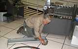
While working on the above, Bill Flora noted that the feed rolls into and through the two
read stations seemed to have detents. We all got our fingers in there and felt the very definite
"detent" or negative lump once per revolution.
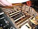

Tapered pin removal is regarded as an art.
Not enough impact on the drift (the clyndrical tool use to
push on the pin) and the pin does not move, but starts to mushroom and become more difficult to remove.
Too much impact on the drift, and you can bruise hole in the shaft.


Since Grant had not come by when we left (about 4:00), ??? took the shafts home.
Grant came by about 5:00 and found no one and no shafts :-((
The second (Sellam's) keypunch works, but Bob Erickson was worried that by-passing to open hold coil
on Relay #2 was over heating the low resistance pick coil of this relay. (The original fix suggested by
"Chuck" at dataservice@juno.com.
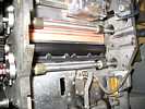
Here is the seven watt bulb, lit during the hold phase of Relay #2 (when a card is registered in the punch station.)

The chassis on the floor at the right of the keypunch is a heavy duty resistor load on "long term loan" from the
PDP-1 guys ;-))
- The coil stayed quite cool, The surface maybe 5 degrees above ambient :-))
- The lamp had about 100 volts across it - should last for years assuming failure by tungsten evaporation :-))
rather than temperature cycling across the phase temperature of tungsten :-((
- The hold in force of the relay armature was judged "just fine" by our panel of amateurs.
With the seven watt bulb, we seemed well within reliable, safe operating range.
"We" (I) decided that we had passed ninth grade basic electricity :-)) Oh Joy!! AT LAST!!
Bob Erickson assumed responsibility for making a proper installation in the keypunch (and getting a proper fuse?
and making proper documentation?, and clearing this with EPA and the environmental impact people?.)
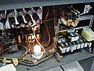
And the final result is imaged to the left :-) Image supplied Jan 24, 2007
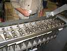
Frank King was testing the 083 card reader, which has been jamming - and got this -
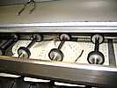
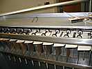
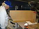
Bob Erickson continued with his project of encasing the 077 in plastic for visibility of the many moving parts,
with minimal risk to fingers and neck ties.
but there was an extraneous "V" at the beginning of every record as viewed in the 1401 memory and printer.
Somehow, the previous contents of the tape are not being properly erased, and are appearing in following reads.
Oddly, there was always exactly one and only one extra "V". ????
TAU Debug Status 12/14/06

It would have been nice if someone would have posted e-mail about the
1401 not being available to be powered up.

Since I could not do hardware debug, I troubleshot a previously recorded
software bug. The "Move Tape" diagnostic program would fall into an
infinite loop repeating the first of about fourteen data records. The
documentation in the Diagnostic manual gave a good hint on the program
segment that was failing. Examination of the diagnostic deck revealed
that a card had been mis-punched by Cardamation. All of the card's
punches were shifted left 7 columns. A seven-byte instruction was thus
omitted. The instruction shifted into that gap unconditionally branched,
so the 1401 was able to execute through the gap without a program check.
This was the second Cardmation mis-punched card found in the new batch
of diagnostics. (The mis-punched card contained all of the data, but the
punches were slightly misaligned.)

I punched a replacement card, but I could not verify the fix due to the
power situation.

Next session:
I will be doing some traveling and will not be available until 2007. See
you all next year. If you need to contact me, e-mail is the best way.

Merry/Happy Christmas/Chanukah/Kwanzaa/New_Year.

Regards,
Bob Feretich
It works so well that we detected a card ( in the diagnostic function tests - punched and printed back east) with a printed column with no punches
We are getting discouraged - maybe time to call in the Pros?
Ron Williams suggests that we seem to be restricted to flat plates, shields, end plates, etc.
Examples could be - a plastic on an end of the 1401,
- plastic replacing the side doors of a 729 tape drive, etc.
(Ron Williams only had to correct a few bits as they were being toggled in :-))
Go to January 2007
go to Team Bios

