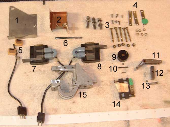
Allen Palmer took a prolay apart (mostly)
Allen needs to correct my informal names & functions!

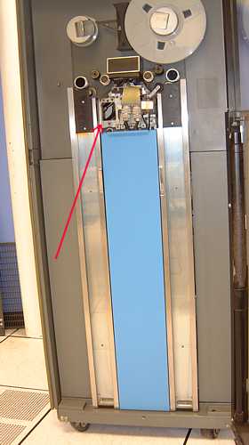
729 with left Prolay removed
The Prolay assembly moves to push the tape against the turning capstan to make the
tape move.

Left Prolay

The correct number of parts displayed is 64 :-))
|
Fun along the way :-))
** John Van Gardner sent the following 5/3/2005
|
Ed,
I was in the first 1401 class in Endicott in 1960 and became the Specialist for the southeastern US. Another retired Support Specialist, Terry Judkins, sent me the URL for the site. I was looking at the last entry showing a Prolay disassembled and it brought back many memories. The shield #1 is to keep the magnetic field from the prolay coils from partially erasing the data on the tape which is only a small distance from the prolay when loaded. I believe it was made of MuMetal. If you do a google you will find many places that still sell the stuff. The AeroShell 14 was used a lubricant to prevent the fretting corrosion that occurred on the armature pivot. t occurs on any shaft that just rocks back and forth not rotating enough to keep the lubricant spread around the shaft. In the beginning we used IBM #6 and sometimes the armature would actually seize. Let me give you some of the proper part names. The coil #5 was called the neutral coil as the core #14 was the neutral core. You had a "Go" coil, "Neutral" coil, and "Stop" coil. The armature #12 originally had a hump on each side of the pivot hole. To remove the arm and armature the whole prolay had to be disassembled. The shims #4 were not originally in a prolay. Two CEs, one from New Orleans (I don't remember his name) and one (Herb Owens) from Baltimore won maximum suggestion awards. One for adding shims (he used a piece of IBM card) to give more travel to the arm causing more bite to the capstans. Prolays without the shims didn't last long before the minute amount of wear would reduce the bite. The other CE took some armatures to a local machine shop and had the hump ground down enough to allow the arm to come out of the prolay without disassembly. This saved and enormous amount of time as we were having to clean and lubricate all the prolays once a week on the 705 Mod III at Lockheed. The joke there was our week consisted of Monday, Tuesday, Prolay, Thursday, Friday. I don't remember which CE came up with which idea but the rest I do remember because of the large amount of money they got. Engineering fought tooth and nail trying not to adopt either suggestion saying it would not work but both CEs had proved it would in a customer account. Herb worked for a very powerful Branch CE Manager named Roy Dailey and he rammed down their throats. Roy later became our District manager in Atlanta I had a similar experience with him and Endicott about the 1401. One of the hardest 729 bugs I had was on an assist trip. Bill Kelly (Years later the 3081 Specialist for our area) was a new CE. He was trying to install a new 729 on a 1410 system. He could not get the start time one the right side to come up in less than 5 MS. We began by adjusting the prolay to move the tape and backing off until the tape stopped. We had no air gap you could see but the start time was still too long. Next we swapped components one at a time between the two sides of the machine. Nothing we did helped. I was standing at the rear of the machine just staring at it when I noticed the cable going to the neutral coil Jones plug on one side of the machine was different than the other side. The side that was working had a cable made up of yellow wires laced with waxed serving twine. The side that was failing was using a wide flat black ribbon cable. It looked like the plant changed the type cable they were using and they started in the middle of this machine. I don't know why I decided to do it but I checked the wiring of the neutral socket and found the two wires were reversed. We unsoldered the wires and swapped them and it fixed the problem. With the wiring error, when the neutral coil was de-energized and the start coil energized, the collapsing field in the neutral coil was bucking the field in the start coil slowing down the armature movement. We reported the trouble to the plant but we never found out if that was the only cable that had the wires reversed. Please pass this on the the guys working on the 729s.
Van Gardner
|